Product Development and Additive Manufacturing
Description
With the ubiquity of 3D printing on the rise, I found myself using the technology personally as well as in engineering courses.
As an individual I have built, calibrated, upgraded, and used multiple FDM printers. Upgrades range from additional frame elements for enhanced rigidity to new control boards and steppers, extruder and hot end swaps, bed levelers.
As a student I have used various printing technologies to manufacture components for labs and UNF’s Senior Capstone Design (more on this later)
During this process I have learned a lot about this technology specifically, but I have also added context to manufacturing in general with a real world idea of what affect design, scale, and alignment have on a product.
Most recently I have been leveraging 3D printing to aid in product development. In this context, additive manufacturing has been useful to physically prototype parts that will be injection molded or otherwise manufactured in the future without the associated cost and commitment.
Poster Scrolling Machine Product Development
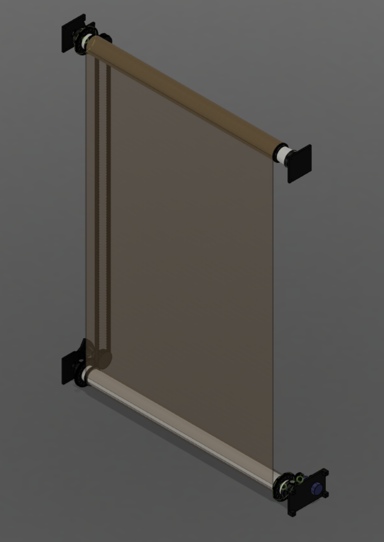
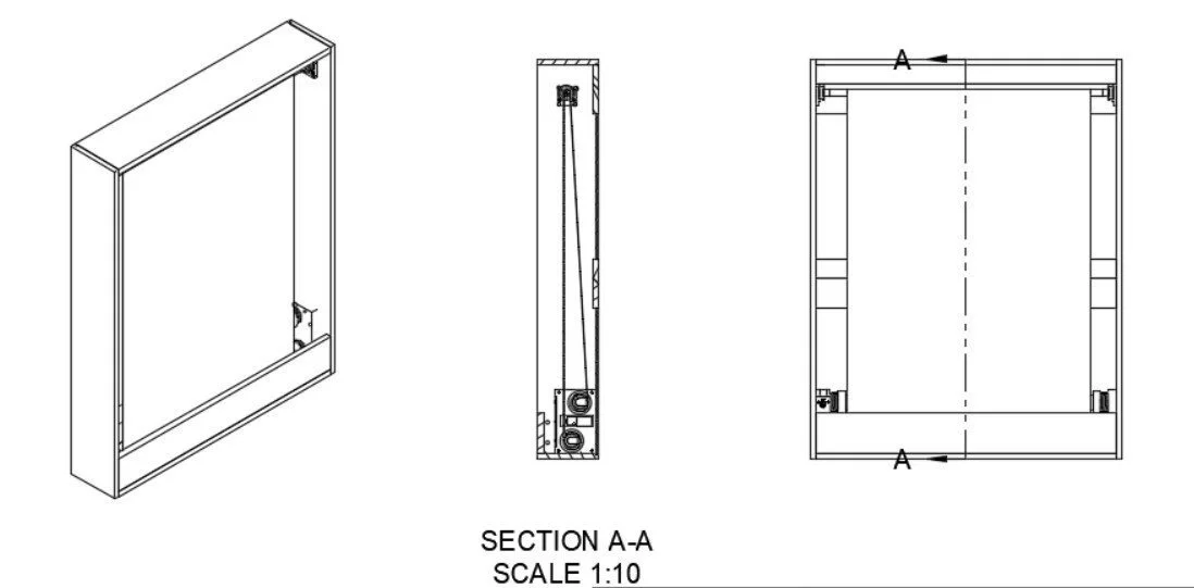
I have been designing and prototyping a wall-mounted device that displays and stores multiple movie posters. This project has allowed me to expand my skills in 3D printing, design for manufacturability (injection molding), microelectronics, machine design, CAD, and programming.
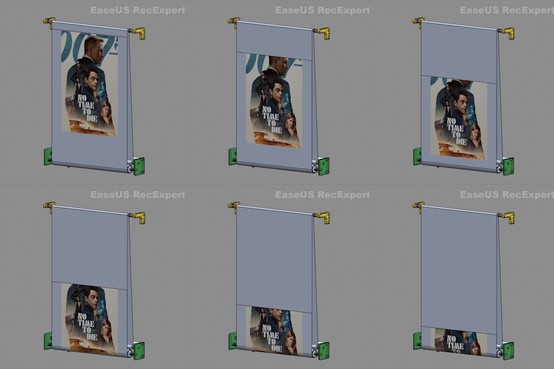
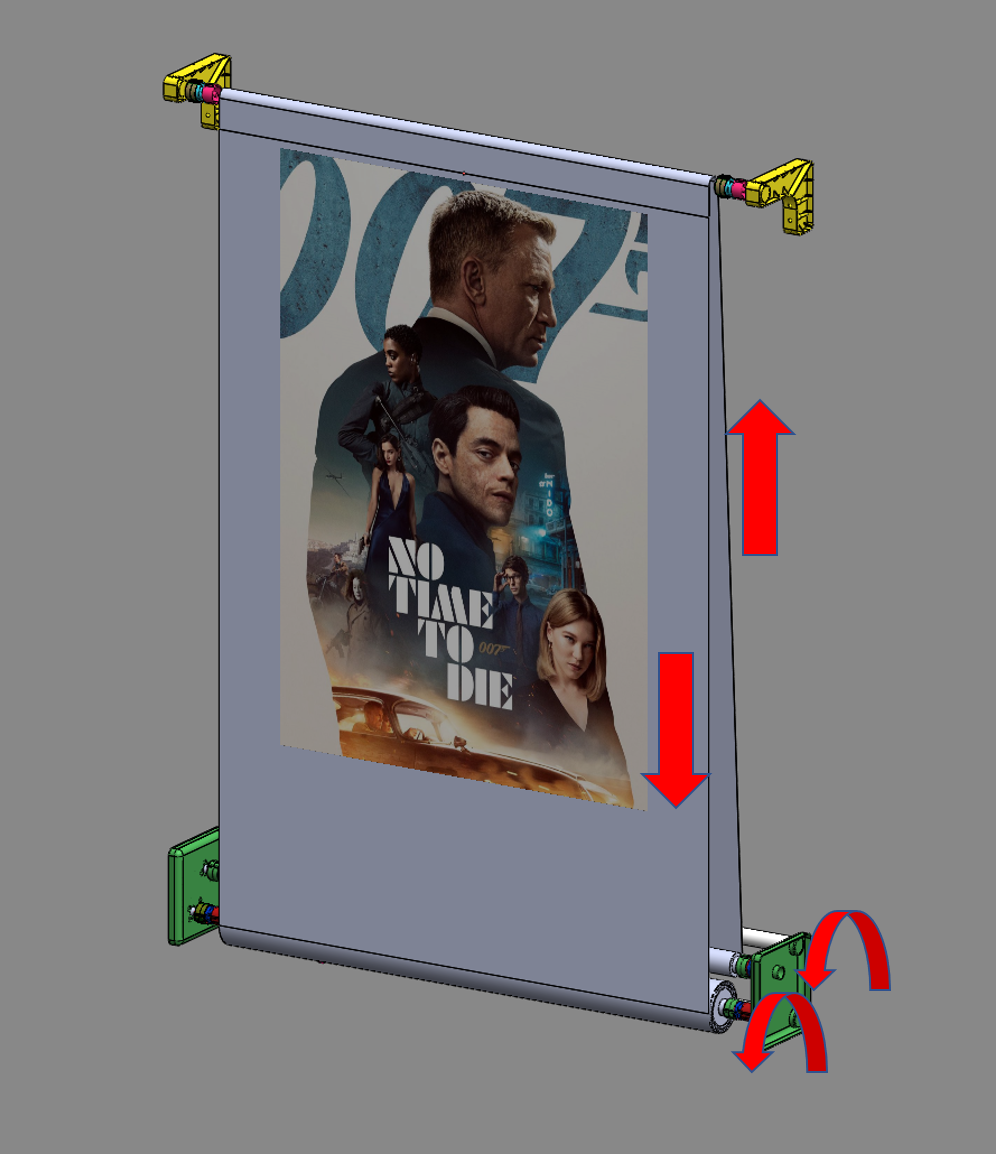
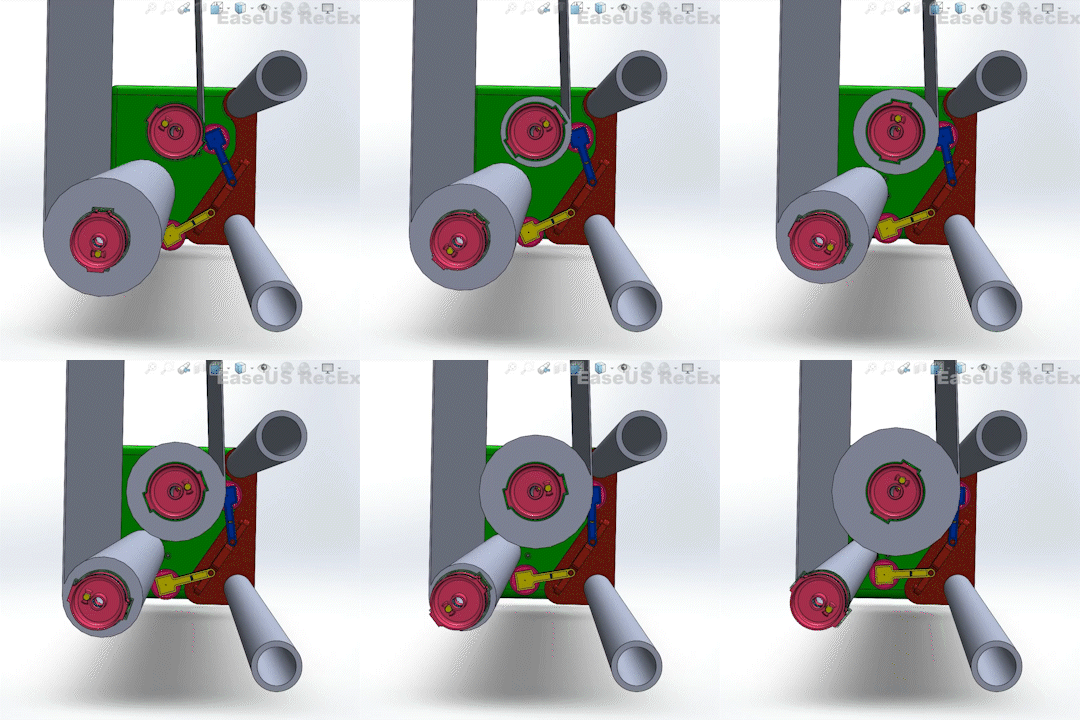
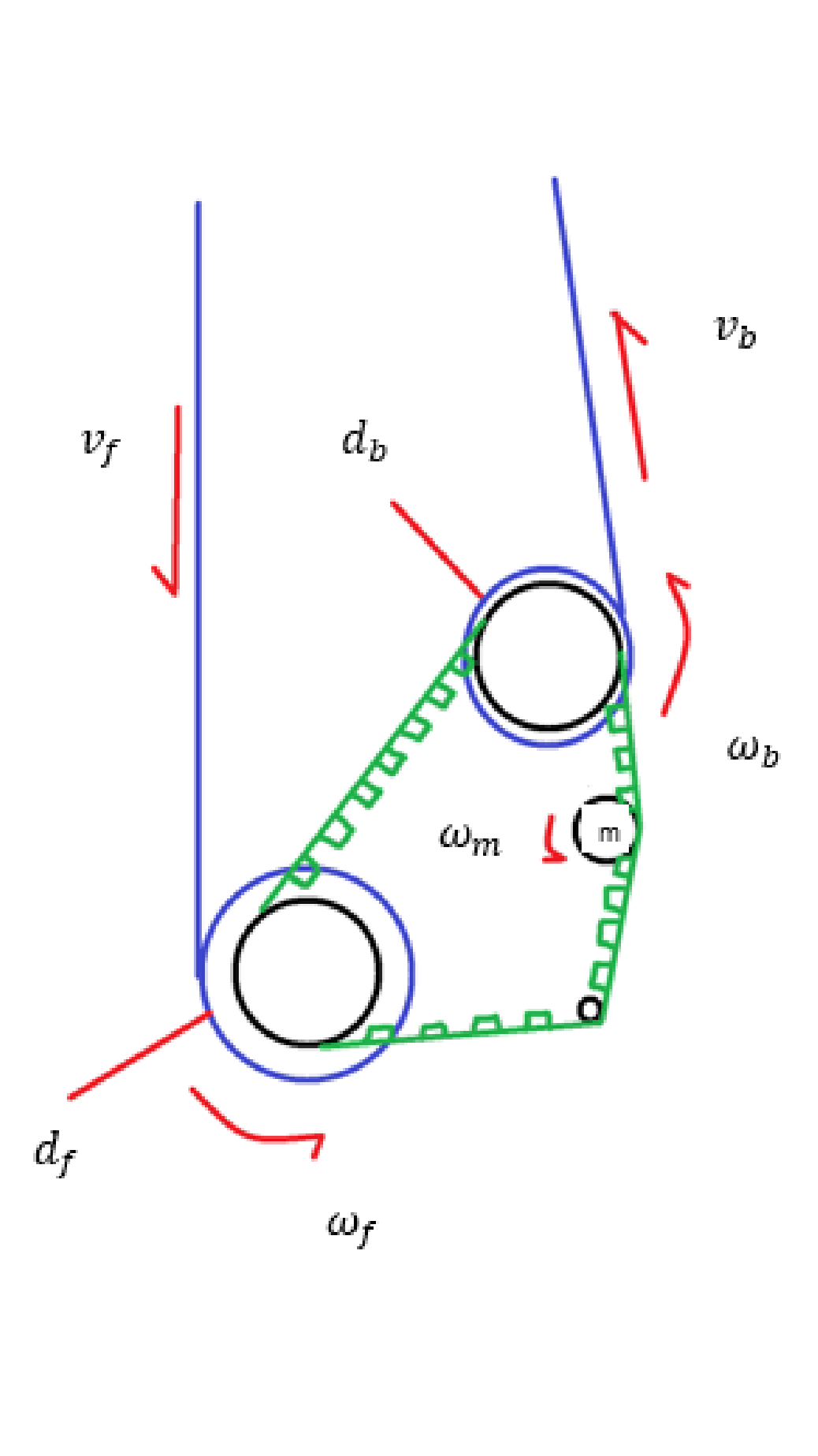
Figure 1 - Device Motion
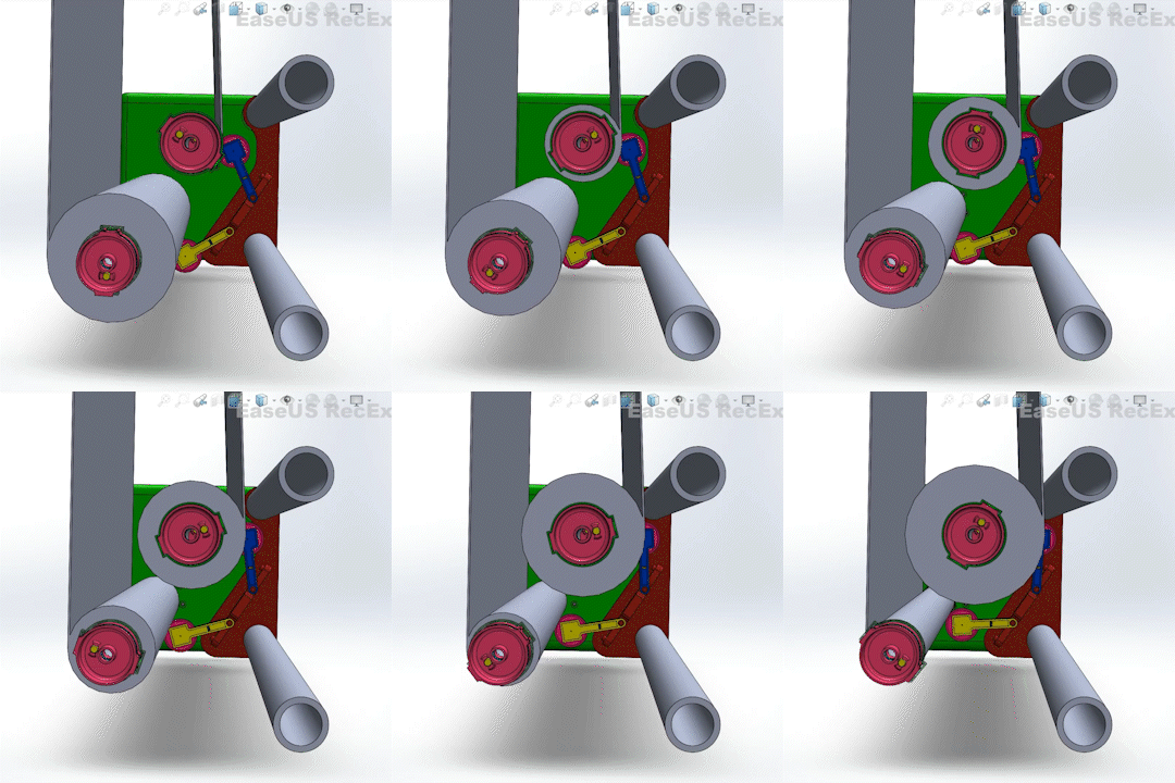
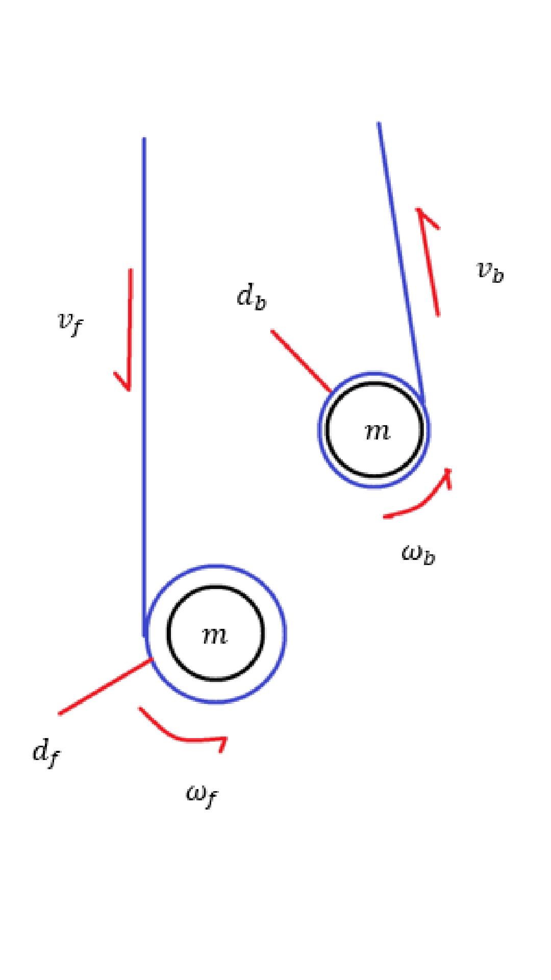
Figure 2 - Take up and Feed
The device employs 2 swappable driven rollers to accumulate (take up) and feed (supply) base material to one another, being careful to maintain tension on the base material.
An idler roller sits atop the assembly to route the base material between the two driven rollers and establish a display plane.
This can be seen in Figures 1 and 2.
Inspiration
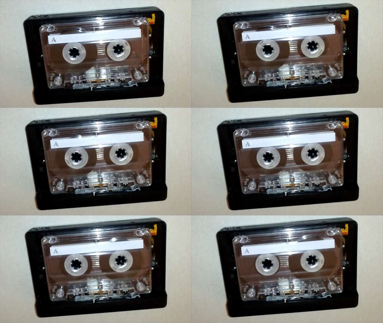
A similar principle is displayed in cassette tapes, wherein the rotational speed of each reel varies to maintain tension on the tape material. Though the mechanism by which this is accomplished is notably different (using mobile fast forward and rewind idlers), the principles can be extended to the poster display device.
Figure 3 - Cassette Diagram
Angular velocity (ω) of each reel varies to maintain the equivalency of linear velocity out of and into each reel.
Diameter of each reel is dependent on the amount of tape fed, thus is continually variable; Leaving only rotational speed to vary when linear velocity is held constant between reels.
Seen in Formula 1
Formula 1 - Cassette Motion
Machine Kinematics
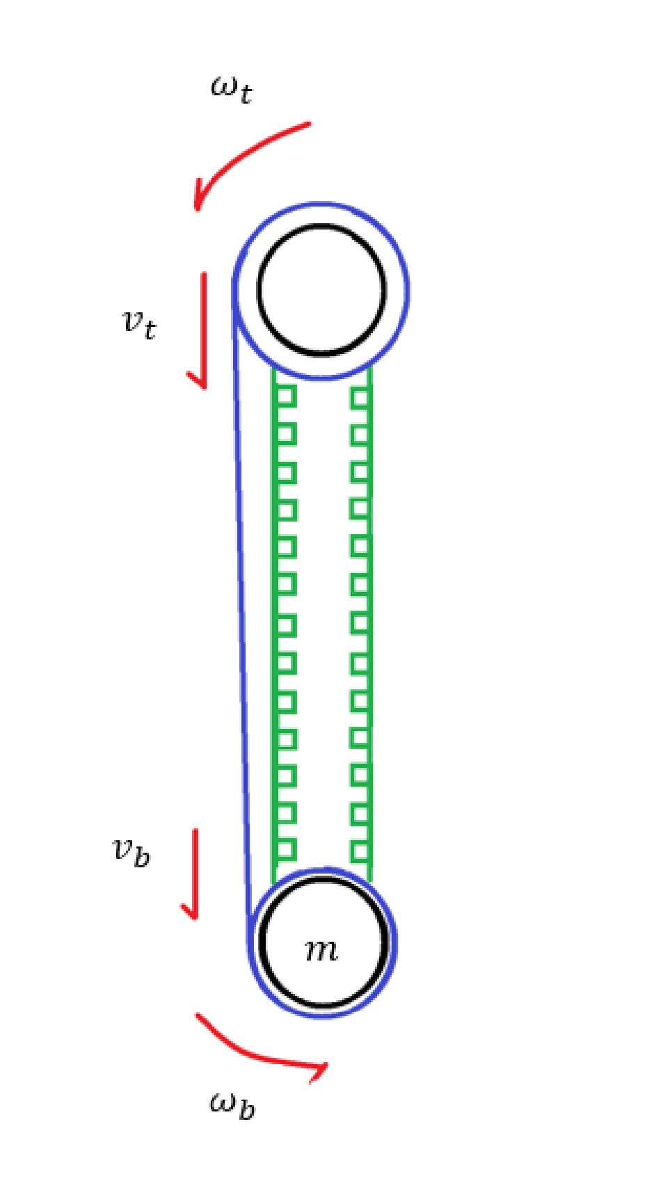
An archimedian spiral approximates the relationships between length and diameter and can be used to extrapolate linear velocity. Each roller can be represented by a spiral.
Similar to the cassette setup, linear velocities are held constant and equal by varying angular velocity. The method by which this angular velocity varies has been a point of iteration. Whether it is pre-determining the requisite motor speeds, or actively detecting the linear velocity output of each roller and controlling them, motor speed MUST vary to maintain tension throughout the display procedure.
Formula 2 outlines the length component of each spiral and can solved to be looked at spiral angle (and thus motor speed) over time to establish a consistent linear velocity output (vf and vb of Figure 4).
Formula 2 - Archimedian Spiral
Figure 6 - Angle Encoders
Over time, through prototyping and kinematic investigation, it became evident that the most accurate way to vary motor speed and maintain material tension would be to actively detect the output linear velocities of each roller.
To accomplish this (Figure 6), two spring-loaded encoder arms maintain contact with the base material. This allows the microcontroller to use PID to vary the motor speed to equalize the linear velocities.
Prototypes
With the power of additive manufacturing, I was able to design and iterate rapidly - testing different designs and configurations.
This was invaluable during the product development process. Without additive manufacturing I would not be able to prototype a device such as this.
Figure 7
Figure 8
Prototype 1
Description
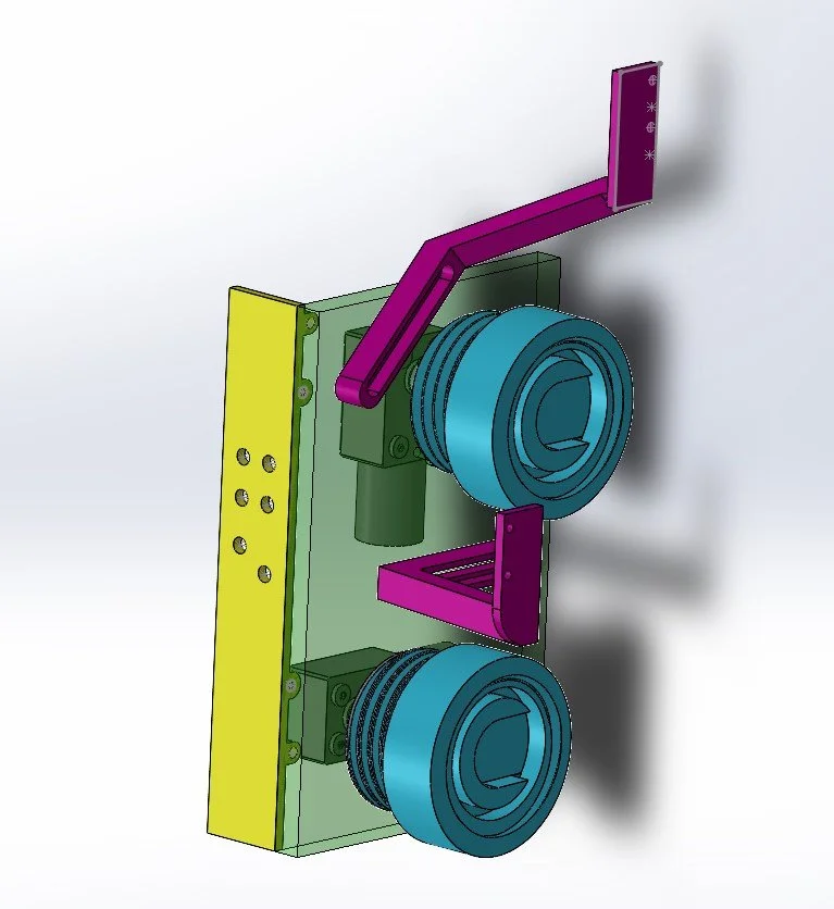
Instead of the two motor setup you see in the current version of the device, this prototype used a singular motor and a large belt to link the rollers.
I also challenged myself to use a motor I already had. This necessitated a gearbox. I played around with a number of gearbox designs to minimize noise and provide the requisite amount of torque.
Issues
In testing this prototype, it became clear that a belt tensioner would be necessary if I was to continue down the single-motor-belt-driven path.
Yet unseen were also issues with the disparity between the linear velocities off of each roller resulting from equivalent angular vel. Now, this makes complete sense because of the items discussed in the kinematics and inspiration sections.
Prototype 2
Description
Though prototype 2 fails to rectify the issue of linear velocity disparities, it does attempt to rectify the belt tensioning issue.
A few iterations took place to try different ways of interfacing between the pinion and belt idler as well as cantilever and fixed support.
Issues
Though the issue of belt tension was mostly solved, slip still occurred occasionally; necessitating Prototype 3.
Figure 8 - Prototype 2
Figure 9
Figure 10
Prototype 3
Description
Prototype 3 consolidates the assembly into one enclosure and drives both motors with a single small belt.
This prototype leverages a similar idler to the one seen on the current version of the device.
Issues
The mitigation of the issues experienced in the previous prototypes finally made the linear velocity mismatch evident.
This necessitated the dual motor design seen in the current version of the device.
Prototype 4
Description
Prototype 4 is the first prototype to utilize two motors. This allows for the independent drive of each roller. In this case, the motor speed was governed directly by the Archimedean spiral equation. In code, an array of deltaL values were calculated based on iterated angle values. This function served as the velocity function of the machine. The integral of this yields the position function and can be used to calculate the amount of angular displacement from each roller that is necessary to maintain tension and goal position.
Issues
This method got very close to working, but in its use of inflexible hard coding was unable to guarantee repeatability throughout the display procedure. Slack would still remain in the base material after many of the rotary moves.
This necessitated a revision to the calculation of the moves between display stages.
Figure 11
Other Additive Manufacturing Experience
Fixture Mold
As a part of UNF’s Senior Capstone Design, my team and I 3D printed a positive of our desired fixture as a part of the casting mold. These prints were to be post processed using bondo and hand sanding.
This experienced again showed the advantages and disadvantages of 3D printing as a manufacturing technique. The speed and cost associated with 3D printing proved much faster and cheaper than CNC milling the fixture out of a larger piece of polymer stock. However, 3D printing, in this case, could not achieve structural components (that is, of the correct material properties) and necessitated a secondary casting process.
Air Turbine
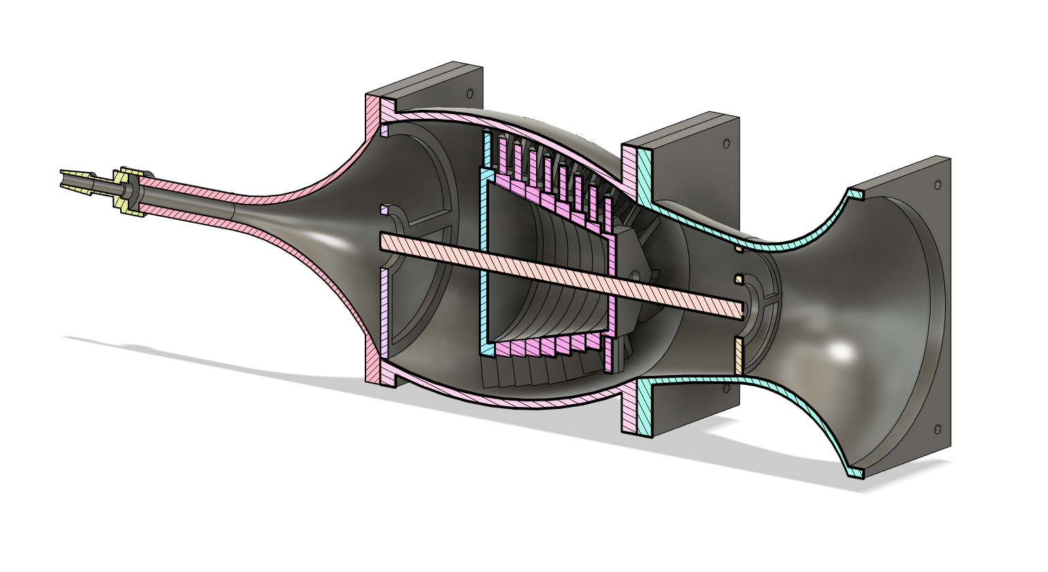
3D Printed Air Turbine
To build initial familiarity with the technology, students were tasked with designing and manufacturing an air turbine, The above image shows the multipart assembly created. This design allowed for the incorporation of pre-designed standard parts (air hose barb) as well as real world parts (bearings, screws, etc).
Related Skills
Mechatronics
Product Design
Machine Design
CAD (Solidworks, Fusion 360, and NX)
3D printing
Design for Manufacturability
Design for Assembly
Microelectronics
